
Modal Space - In Our Own Little World
I ran one test with an x-excitation and can see some modes and another test with a y-excitation and see some different modes. Could I use an oblique angle instead?
Well, that's a very good question. It is one that comes up often in terms of running modal tests with a shaker excitation. Of course it is totally acceptable to run one test with a shaker at some oblique angle to the structure. But the only thing we need to be careful about is to assure that we don't select the reference point at the node of a mode.
Let's talk about this a little more. Let's start this discussion with a simple structure that has mode shapes that are very directional in nature. Now just what do I mean by that. That means that the response of the structure is primarily in one direction with very little or no response in the other directions for a given mode of the structure. Yet another mode of the structure may have response in a different direction than the first mode with little or no response in the other directions.

Figure 1
To illustrate this, let's consider the very simple frame shown in figure 1. We see that mode 1 of the structure has motion primarily in the horizontal direction with very little response in the vertical direction. However, mode 2 of the structure has motion primarily in the vertical direction with very little motion in the horizontal direction. We can also see that mode 3 and mode 4 follow the same trend. Mode 5 and mode 6 have motion in both the horizontal and vertical directions with the vertical direction being slightly more predominant.
If we look at a drive point measurement in the vertical direction (as shown in figure 2) over the bandwidth of the first six modes of the structure, we notice that there are only 2 peaks that are visible in the measured frequency response function. Yet we know that there are 6 modes in this frequency range. And if we took a drive point measurement in the horizontal direction we would also notice only 4 peaks. But upon closer examination of the measurement, we would notice that the first two frequencies of each of the measurements is different.

Figure 2
So now we can see that the modes cannot be seen in every measurement. That directly implies that if we were to select either one of the two measurement points shown as a reference point then clearly we would not see all the modes of the structure. But just why does that happen.
Let's recall the equation for the frequency response function:
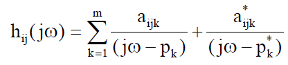
which (for illustration) is expanded for 3 modes:

This equation is described by the residues (in the numerator) and the poles (in the denominator) for each of the modes of the system in the formation of the frequency response function. We also need to remember that the residues are directly related to the mode shapes (and a scaling factor) as:

so that the frequency response function can be written either in terms of residues or mode shapes. When written as a mode shape, then it becomes very clear that if the value of the mode shape at the reference point is zero (or almost zero) then that mode will not be seen in the frequency response function. So the trick to performing a good modal test setup is to always select a reference point where all of the modes can be seen all the time from that reference point. But sometimes this is easier said than done, especially when I am not sure what the expected modes of the system are going to be. (Its always easy being a Monday morning quarterback.)

So now let's look at the first 4 modes separately. Then the optimum reference location is easily seen to be the point on the structure where the mode shape value is largest. But I quickly realize that the point is different for each of the modes. The trick is to select one point where each of the modes can be observed "reasonably well". The point where most people get hung up is in trying to think in terms of our simple rectangular coordinate system - with x, y and z directions.
What would happen if I tried to apply a force to the structure at a point that has a 45 degree angle to my global rectangular coordinate system. Would the reference point shown be suitable to be able to measure all the modes of interest?

The best way to answer that question is to look at the equation that forms the frequency response function. We quickly notice that the equation can be written in terms of mode shapes. When we consider the first 4 modes of the system, we notice that each mode has a component of response in this 45 degree angle. This means that this reference point would be suitable for measuring the first 4 modes of the system. However, if I take a closer look and consider modes 5 and 6, then I will quickly discover that these two higher modes will not be measured at all from this reference point. This is because, the center point on the cross member is a node point for both modes 5 and 6 of the structure.
So we could pick any point on the structure including an angle relative to the global coordinate system. The only requirement is that the mode shape should have a significant value in relation to its mode shape; if the reference point selected is a node of a mode then I will not see that mode in the measured response. One last thing to quickly mention is that in order to obtain valid "scaled mode shapes", a drive point measurement is necessary. (We will talk about mode shape scaling in a future article.) This means that the response must be measured at the same point and in the same direction as the applied force - this also applies to a reference measurement which is taken at an angle to the global coordinate system.
I hope this explanation helps you to understand that you can pick any angle for the reference - just as long as its not the node of a mode. If you have any other questions about modal analysis, just ask me.