
Dual Excitation Shaker Push-push Testing
Dual excitation shaker systems are commonly used to test long or heavy devices under test (DUT). When the device under test is very long or too heavy, a single shaker cannot perform the test because of oversized dimensions or a large driving force. Thus a dual excitation shaker system is arranged as the solution. Users can fix the longer sized or heavy DUT horizontally or vertically on top of a dual excitation shaker system. Common arrangements are horizontal push-push, push-pull, and vertical.
Here we examine the details of dual excitation shaker system testing. In this case, two shakers are placed horizontally, side by side. Driving bars are connected between the shaker armature and slip table for each shaker. Technically, these two shakers are placed opposite to each other and is referred to as Push-push to differentiate from the face-to-face configuration which is referred to as Push-pull.

Figure 1. Dual excitation shaker Push-Push configuration with fixed U channel beam
The dual excitation shaker system includes rails under the shakers. The rails allow one shaker to move from side to side while another shaker can move back and forth. This allows users to place the shakers in different configurations. The following photo shows the rails under the shakers.

Figure 2. Rail system allows shakers to be rearraged in different configurations
Sensors are attached to the front side of the slip tables. Due to the nature of the shakers facing each other, the sensors are also opposite to each other. To move both shakers in phase, the phase between these two control sensors must be set at 180 degrees. If this is mistakenly set at 0 degrees, damage may occur to the shaker system.

Figure 3. Control sensor placement
The EDM MIMO Random controller is used to control the dual excitation shaker system. Crystal Instruments provides a wide range of vibration control including MIMO Random, MIMO Sine, MIMO Shock, MIMO TTH, MIMO SRS, and MIMO TWR.
The test setup starts with the shaker configuration. Select the dual shaker push-push configuration and label the drives as X1 and X2. The profile is a scaled DO-160 random profile with 3 grms as displayed in following graph.

Figure 4. Control Profile
The control method is set to “Mag and Phase”. To run both shakers in phase, the phase between the two controls is set to 180 degrees. This is due to the nature of having two control sensors placed opposite to each other.
Since the U channel beam is rigidly fixed on top of two slip tables, it is preferred to have no rotation among the shakers. To accommodate this hardware connection, the sequential pretest is used. With this set up, one shaker will drive the system at a time. A single column of the Frequency Response Function of the controls vs. drive will be calculated. When two shakers finish the pretest, a 2x2 FRF matrix is constructed, which will serve as the governing matrix for the forthcoming MIMO control.
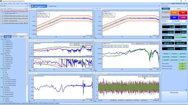
The following is a screenshot of MIMO Random test during operation. The control channels are under great control.
For more details regarding EDM MIMO Control, please check the Crystal Instruments Multiple-Input Multiple-Output vibration control section.