
Digital Input and Output Communication on the Spider Platform
Digital Input and Output (DIO) is the most popular interface for communicating and interacting with external instruments. Each digital input and output channel has two states: high or low. The Spider can respond to the state of a digital input channel from an external instrument or send a digital output to an external instrument. The change of the state of DIO is handled directly by the digital signal processor (DSP) without an additional exchange of commands to achieve the shortest response time. This feature is ideal for applications that require an immediate response from external equipment or a Spider system.
The following sections provide an example of using the DIO to communicate with an amplifier, a data analyzer, and cameras while running a vibration control test with EDM 9.0 software. It also includes the usage of event-action rules and CAN bus features.
Testing Requirements
Start an amplifier before pre-test
Record all data of the test, including pre-test, with the Spider controller
Record all data of the test with a data analyzer
Record the video of the UUT movement during the test with cameras
Monitor the temperature of UUT via CAN bus. Stop the test when the temperature of UUT is over 70 °C
Send an SMS message and email when a test aborts or completes
Turn off the amplifier at the end of the test
Devices Operation
Start the amplifier of the shaker system before pre-test by Digital Output.
Trigger the data analyzer to start recording.
Start camera recording
After a test completes, turn off the amplifier, analyzer, and camera.
Digital Input and Output Configuration
Configure digital input and output channels
Give each pin a name and set the default status of digital output according to input definitions of an amplifier, analyzer, and cameras.
Digital Input pin #9: Test Starts: Start the test
Digital Input pin #14: Analyzer Off: Monitor if the Analyzer is off.
Digital Input pin #15: Cam 1 Off: Monitor if camera 1 is off.
Digital Input pin #16: Cam 2 Off: Monitor if camera 2 is off.
Digital Input pin #17: Stop Test: One digital signal to stop all devices, controller, analyzer, and cameras
Digital Output pin #01: Amplifier: Low->Off, High->On
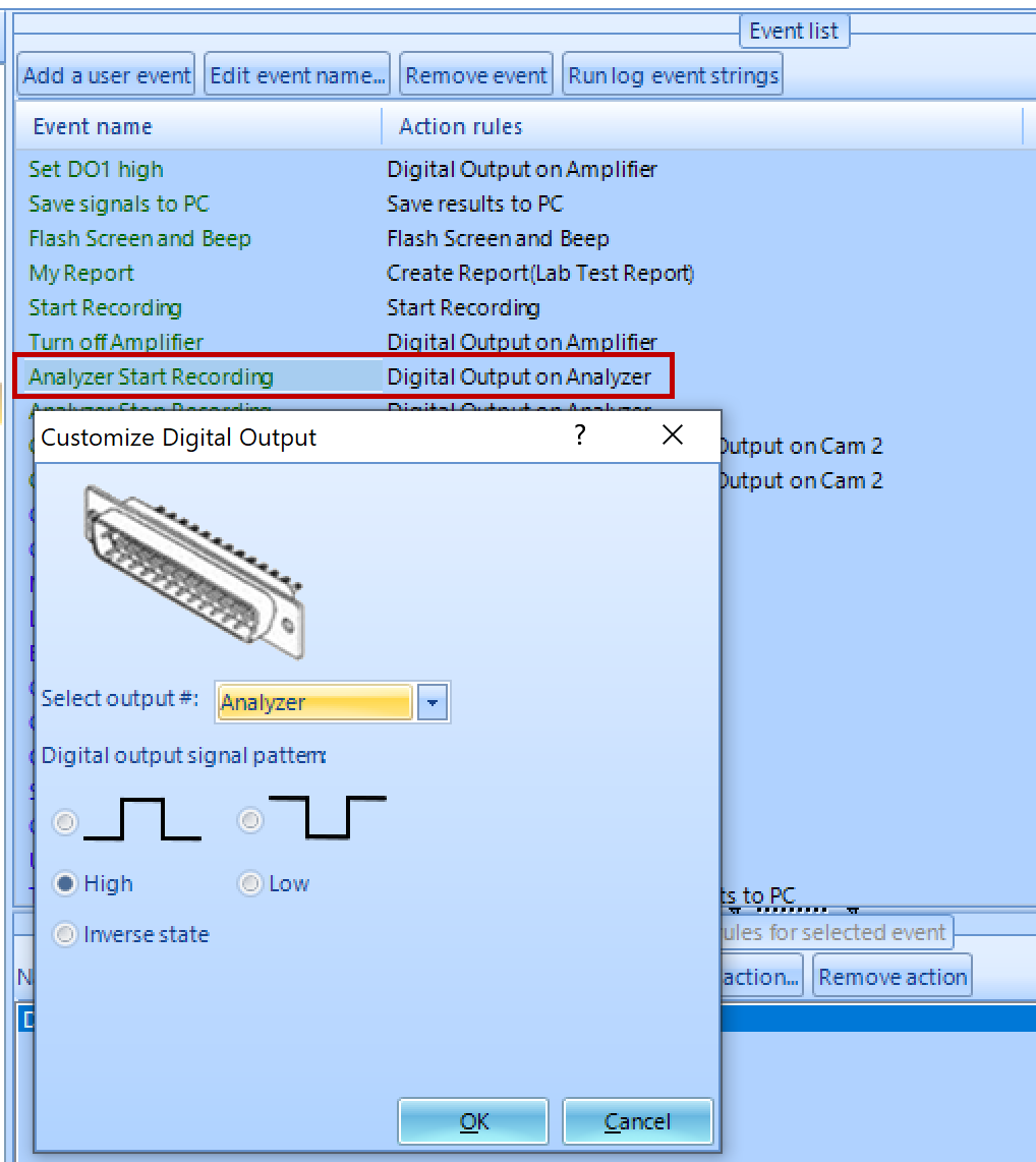
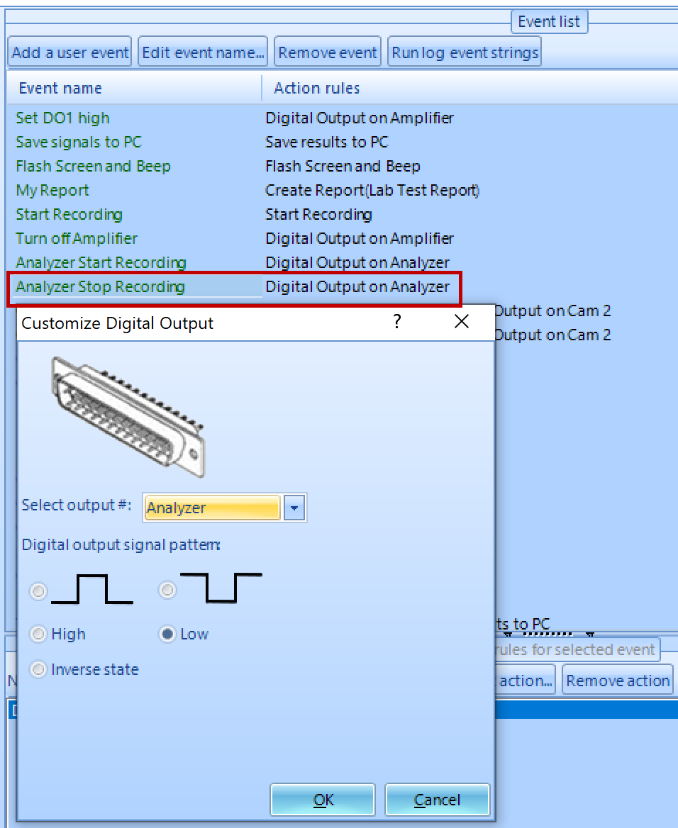
Digital Output pin #02: Analyzer: Low->Standby, Low-to-High->Start recording, High-to-Low->Stop recording
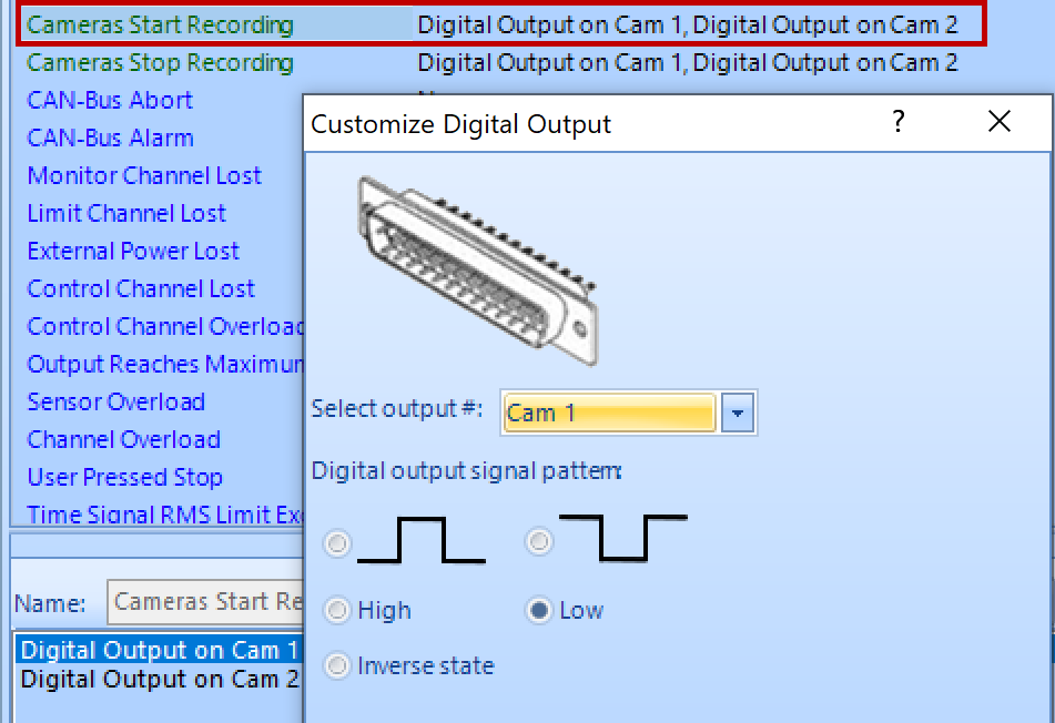
Digital Output pin #03: Cam 1: High->Standby, High-to-Low->Start recording, Low-to-High->Stop recording
Digital Output pin #04: Cam 2: High->Standby, High-to-Low->Start recording, Low-to-High->Stop recording
Click “Apply DIO setting” after all changes are done.

2. Configure a Digital Output to start the amplifier of the shaker system before pre-test.

3. Configure to start recording before pre-test

4. Configure event-action rules:
A Digital Output triggers the data analyzer to start recording
A Digital Output triggers the data analyzer to stop recording
5. Configure event-action rules:
A Digital Output makes two cameras start recording
A Digital Output makes two cameras stop recording

6. Configure event-action rules: a digital output turns off the amplifier

7. Set CAN bus signal abort limit
Add action “Stop the test” to the event

8. Send an SMS message and email when a test aborts or completes
To send an email as an SMS message, contact your phone service provider to see if it is supported.
Configure an event to send email/SMS message

Add the “send email/SMS message” action to the “User Pressed Stop” event.

9. Schedule Configuration

Simply trigger Digital Input pin #9, and the above schedule will be executed. The whole process of the vibration control test is automated and initiated efficiently with one digital signal.
Questions? Contact the Crystal Instruments support team for additional details.