
Common-Mode Rejection Ratio
The common-mode rejection ratio (CMRR) specification defines how well a differential amplifier rejects common-mode signals. A common-mode signal is the same (common) to both conductors in a typical two conductor connection (signal conductor and ground conductor). Differential amplifiers are designed to amplify the difference between the two conductors:
vout = A (v+ - v-)

The output voltage is equal to the gain, A, multiplied by the difference between the two terminals of the amplifier. This design inherently creates an attenuation of signals that are common to both conductors because the output amplifies the difference between the input terminals. If the voltage at each terminal is the same, the quantity in parentheses is zero. However, common-mode signals are not exactly equal on both conductors, so they will not be completely eliminated. This means we need to quantify the amount of attenuation, and the CMRR does that with the ratio of the differential gain to the common-mode gain:
CMRR = | ADM / ACM |
The absolute value is only a convention, and because many specs are stated in decibels, a positive sign vs. a negative sign in front of a specification changes by swapping the numerator and denominator (THD is negative, dynamic range is positive). Since the specification has “rejection” in the name, the negative sign is implied so it is discarded.
The following figures illustrate and explain the possible types of connections between signals and amplifiers. For the notation, vin refers to the positive terminal of the signal source (the opposite side is -vin), and v+ , v- refer to the positive and negative input terminals of the differential amplifier.
A common-mode signal is the same (common) to both of the amplifier’s inputs. In the ideal case, the voltages at each terminal are equal, so the output would be zero.
vout = A (v+ - v- ) = A ( vin - vin ) = 0

A differential-mode signal has both outputs of the source connected to the amplifier. The source’s outputs are 180 degrees out of phase, which causes the gain to increase by a factor of 2.
vout = A (v+ - v- ) = A ( vin - (vin) ) = 2Avin

A single-ended signal can be drawn similarly to a differential mode signal, but the distinction between them is that a grounded connection is used. Ground is ideally at zero potential, so the output is just an amplified copy of the input signal.
vout = A ( v+ - v- ) = A ( v+ - v_ ) = Avin
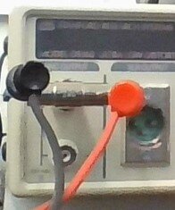
The CMRR can be measured by configuring an output channel with a BNC T-adapter in addition to a cable that has a normal BNC connection on one end and is split on the other end, shown in the picture on the right. The other end of the cable (terminated by the BNC) is connected to a Spider-80X, or any similar product.
In EDM, the input channel settings must have the input mode set to differential and the input range set to Full. The following configurations are also made before measuring the CMRR:
Frequency Range = 46 kHz
Block size/Line = 16384/7200
Window = Hanning
Overlap ratio = No Overlap
Average Mode = Exponential
Average Number = 8
Voltage dB reference = 20 (Global settings / Engineering Units)
After the settings have been configured, a common-mode signal of 10 V at 1 kHz is generated from the source. The amplitude measured by the Spider-80X should be -6 dB because of the voltage dB reference, which means 6 dB should be subtracted to the measurement (nothing should be subtracted if the signal is 0 dB, but the common-mode range does not go to 20 V). However, the differential amplifier introduces a gain of 2, which adds 6 dB back to the CMRR specification, so using a 10 V signal means no adjustments have to be made.
The following screenshot from EDM shows the result of the preceding steps, resulting in a CMRR of 70 dB at 1 kHz.
