
Modal Space - In Our Own Little World

Why can’t I run a modal test with one big shaker and just “crank up the signal”?
That isn’t a good idea - Let’s discuss this.
Why can’t I run a modal test with one big shaker and just “crank up the signal”?
That isn’t a good idea - Let’s discuss this.
OK – so we need to talk about a few things here. Many times people who get involved in modal testing sometimes come from the “vibration qualification world” and have a completely different mentality compared to the “modal world”.
In vibration qualification testing, a large shaker is used and a test article is normally hard mounted to the top surface of the armature and then some base excitation is applied and usually monitored by controlling some prescribed acceleration. The device under test (DUT) is normally subjected to some operating environment, generic spectrum or some excessive environment to determine if the equipment is suitable for the intended service. A typical test schematic is shown in Figure 1 showing the shaker system and a test article mounted to a fixture and expander head which is all attached to the shaker armature.

Figure 1 – Typical Shaker Qualification Test Set Up
This is a completely different test than what we try to do with modal testing. In modal testing, the shaker is attached to the structure with a long rod commonly called a stinger or quill. The force imparted to the structure is measured with a force gage or an impedance head mounted on the structure side of the shaker exciter set up. This is shown in Figure 2.

Figure 2 – Typical Modal Test Set Up
In modal testing, the intent is to use lower levels of excitation and identify system characteristics – the test is not intended to provide operating level input excitations. In fact, if higher levels are used then sometimes nonlinear characteristics of the structure are excited and the overall measurement becomes distorted and not particularly useful for modal parameter estimation.
Now of course it also depends on what kind of structure you are testing. If it is a very simple component of a larger system and the component itself is fairly linear then there is no problem using a single shaker with an appropriate force level specified.
But when the structure becomes more complicated with many components assembled together to form a system, then the ability to provide a force excitation to measure all the locations on the structure to identify the mode shapes can become more difficult. This can then be compounded when the various components are attached with mounting devices to isolate all the components from each other. The problem becomes that it is very hard to provide an adequate excitation from one shaker location and be able to make adequate FRF measurements at all the response points to be measured. Then it becomes necessary to “crank up the signal” to be able to get measurable vibration at all the response locations. When this is done, then it is very likely that nonlinearities will be excited and then the overall measurement will be degraded.
I have been involved in many tests where this is the case. Just recently, a test on a large propulsion system had an isolation system that was intended to isolated all the components for vibration transmission considerations. The actual data can’t be shown but a laboratory structure with several components attached through an isolation system was used to illustrate the problem with using just one shaker to excite the system.
The laboratory structure is shown in Figure 3 with three plate components attached with isolators to a larger frame structure.
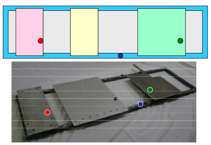
Figure 3 – Laboratory Structure with Isolated Components
A single shaker was attached on the main frame and FRF measurements were made. In addition, a three shaker MIMO test was also conducted to compare the measurements obtained. Figure 4 shows a typical drive point measurement (on the main frame in this case). The FRF in red is related to the SISO test.
Also shown in the figure is the same FRF (black) obtained from the three shaker MIMO test that was conducted with much lower overall excitation applied to the structure.
In looking at the FRF, it is very clear that the SISO FRF obtained is not the same quality as the MIMO FRF obtained using lower overall shaker excitation levels; this is especially true when looking at the coherence. A cross measurement that is even poorer quality is shown in Figure 5 and again the FRF and coherence is seen to be much worse from the SISO test.

Figure 4 – SISO vs MIMO FRF Drive Point Measurement
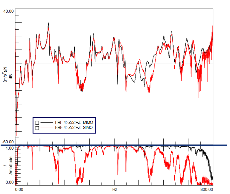
Figure 5 – SISO vs MIMO FRF Cross Measurement
Now this is a very short discussion but in the next article this will be expanded to further illustrate that using one shaker with higher level of excitation is not preferred to the multiple shaker excitation approach with lower excitation levels.
I hope this explanation helps you to understand that using one shaker with the “signal cranked up” will not provide a good measurement overall. If you have any other questions about modal analysis, just ask me.