Sampling Synchronization Through GPS Signals
Crystal Instruments has recently been granted a patent (US 11,611,946) for the methodology used to synchronize signals acquired using multiple physically unconnected data acquisition systems.
In a DAQ where the time accuracy of the sampling clock is not very demanding, say no better than seconds, the time base can be derived from the “computer time”, which can be set manually, through a time server on a network, or through the internet. When the time accuracy of a sampling clock demands millisecond resolution, the digital input paths of the data acquisition system, especially its ADC, must be designed with control from a more accurate time base, such as GPS or IEEE 1588 PTP (precision time protocol). This is necessary to calculate the cross-channel spectrum, or any signal property related to the time delays between all measurement signals.
An ADC requires a clock with a specific oscillator frequency to drive its sampling. The diagram below shows the ADC clock drift in concept, and UTC time stamps which do not drift. Here the ADC clock has a period of more than 10 μs. The drift might be caused by the environment, especially changes in temperature.

Besides the short-term drift of the ADC sampling clock, a DAQ may have an inherent offset when compared against oscillators on other DAQs or when compared against the atomic clock of a GPS. The combination of offset and drift constructs a bias of the clock. For a recording time of a few minutes this bias may not be a major problem. However, if the recording time is as long as hours or days, this sampling clock bias may cause sampled data from different units to have mismatches when comparing the acquired time.
If the ADC sampling clocks cannot be accurately synchronized between different hardware units, it is possible to achieve similar signal processing results if all recorded data are accurately time stamped.
Multiple CI-GRS data acquisition systems can acquire data simultaneously while physically spread out over hundreds of miles, and each system’s ADC sampling clock may have a unique ADC clock offset. These units do not share any direct hardware connections, but each will receive GPS signals.
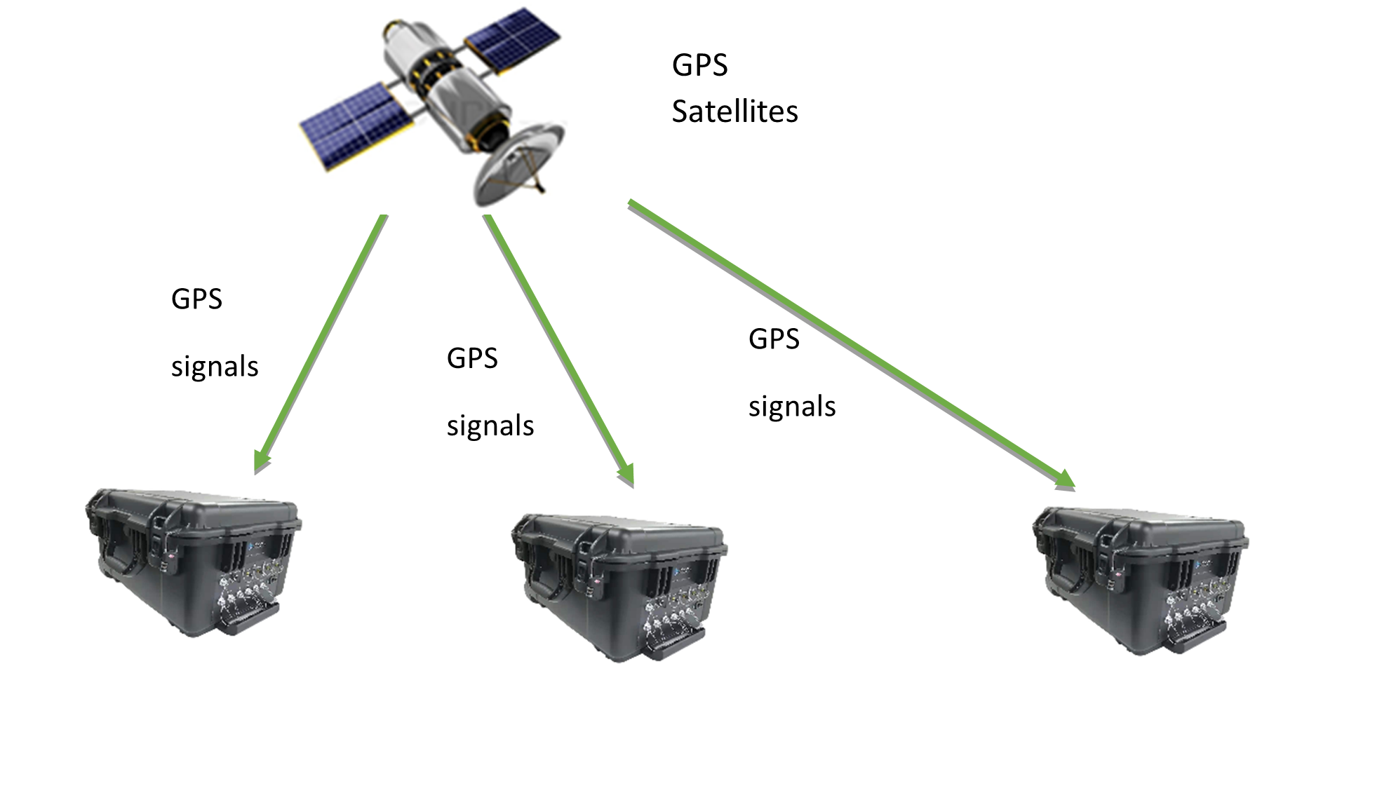
The GPS receiver used in the CI-GRS has 60ns time accuracy 99% of the time. A real-time, zero latency hardware logic is implemented to time stamp the ADC sampling clock with the measured GPS time base.
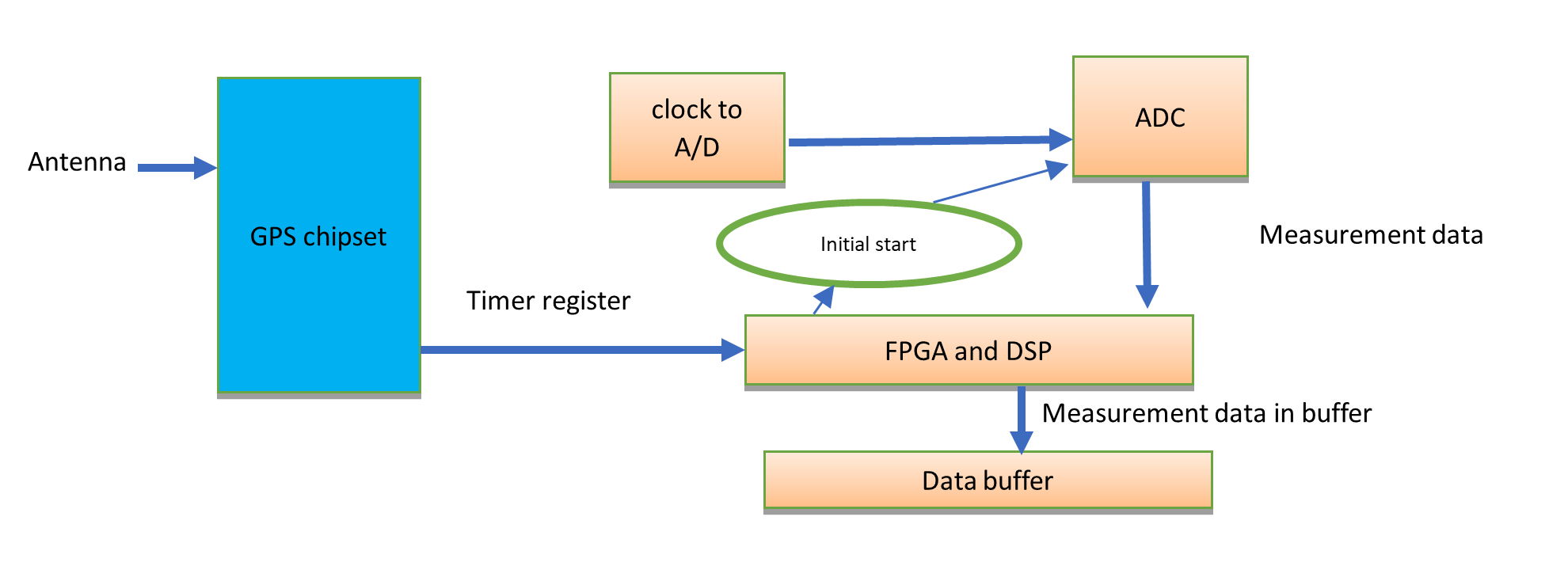
A simplified diagram of how time stamping works in GRS is shown below:
In the following table, the Nominal Time is the local clock time, and the Actual Time is derived from the GPS signals. Both times are associated with one acquired data set.
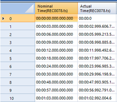
Since we know the error between nominal time and actual measured is mainly an offset instead of a random drift, this offset error can be corrected after the measurement is acquired.
The plot below shows that when an impulse event is recorded by two data acquisition systems with slightly deviated sampling clocks, the signals will be offset by a certain duration even with the same starting time-base.

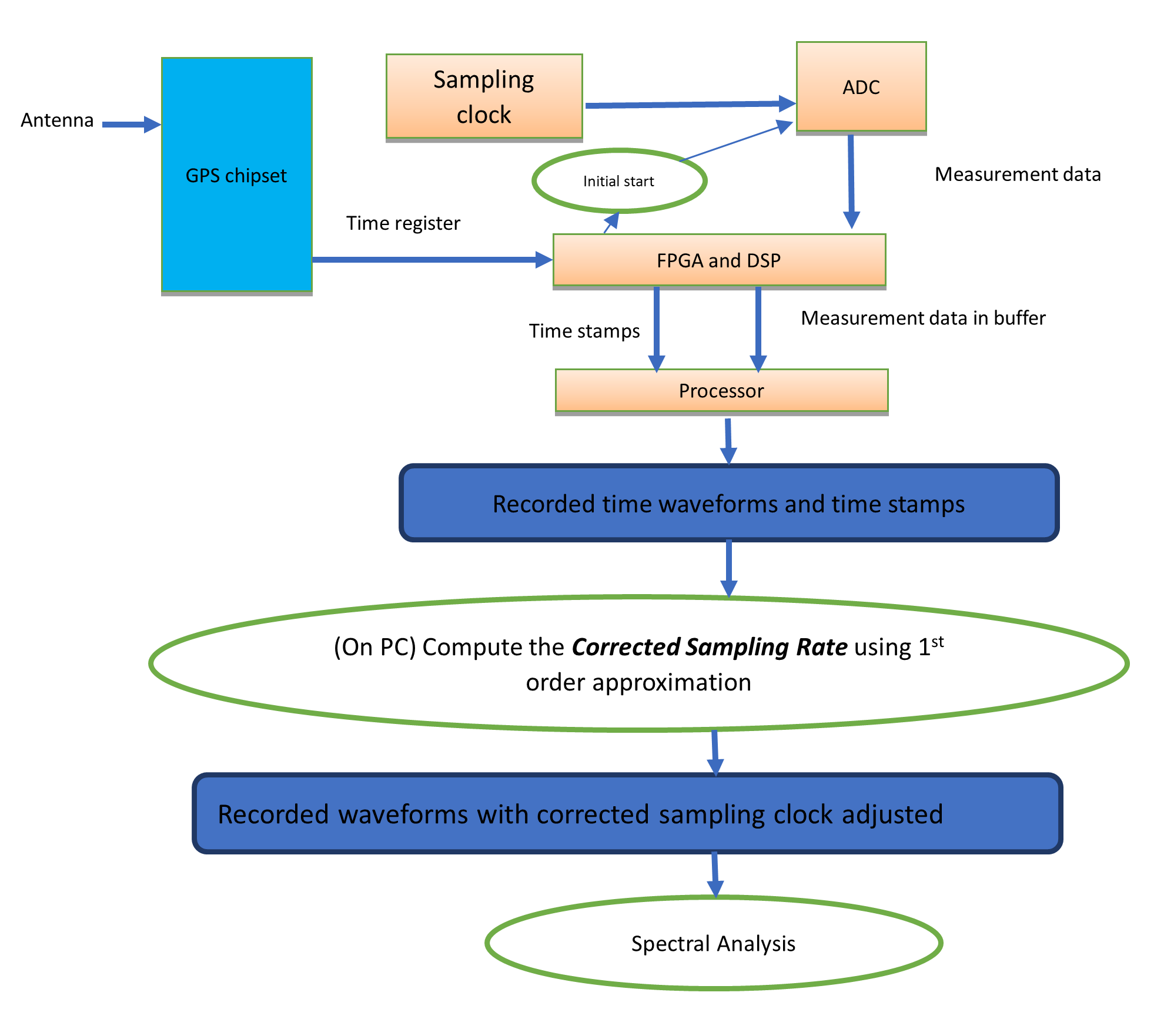
Using Post Analyzer and the time-stamped signals, we can derive a corrected sampling rate by removing the first order error between the local clocks and the GPS time base. Here is the same plot as above, but after the correction is applied.

After the adjustment, all classical signal processing methods such as FFT, FRF (Frequency Response Function), Coherence Function etc., can be applied in the post processing software. The whole process is illustrated in the following diagram.