
New Generation Spider Hardware with 175 dB Dynamic Range
Crystal Instruments continues to push the boundaries of precision measurement technology. Our latest release represents a significant advancement in data acquisition and vibration control technology, featuring comprehensive enhancements across the following Spider platforms:
This new generation of Spider hardware has seen improved performance in the following areas:
Dynamic Range of 175 dB
Noise Floor of 29.7nV/(√H z) at 1 kHz
Total Harmonic Distortion
Crosstalk
Common Mode Rejection
Output Dynamic Range of 145 dB
| Specification | Details |
|---|---|
| Input Dynamic Range | 175 dBFs |
| Noise Floor | 29.7nV/(√H z) at 1 kHz |
| Output Dynamic Range | 145 dB |
| Smallest Precision Output Amplitude | 500 nV |
| THD | -100 dB at 1 kHz |
| Crosstalk | Better than 120 dB |
| Common Mode Rejection | Better than 120 dB |
Dynamic range defines how effectively a system can capture both very small and very large signals without distortion. In essence, it is the ratio between the largest measurable signal and the smallest detectable signal. The Spider hardware accomplishes a 175 dB dynamic range primarily with Crystal Instrument’s proprietary dual-ADC technology. The Spider hardware employs two high-performance 24-bit ADCs per input channel. Each one is configured with a different input gain range, one optimized for low level signals and one optimized for high-level signals. The signals that propagate through each ADC are sampled synchronously and since they are sampled in parallel, the Spider eliminates the need for manual range switching. By measuring the outputs of both converters in real time, the Spider achieves an unprecedented 175 dB dynamic range, capable of capturing minuscule sensor signals as small as 29nV/sqrt(Hz) and as large as inputs up to 20 V without changing the input gain.

Figure 1. High level diagram of the Dual-ADC Architecture
The dynamic range of a DAQ is fundamentally limited by its noise floor, as this defines the smallest measurable signal relative to the system’s maximum input level. The noise floor of Crystal Instruments’ DAQs is characterized by measuring a terminated input to eliminate external signal interference. This setup ensures that any measured signal originates solely from the internal electronics of the system. The resulting data is analyzed in the frequency domain and expressed as voltage spectral density (V/√Hz), where the noise voltage is normalized by the measurement bandwidth. This normalization effectively accounts for the number of frequency bins produced by the FFT, ensuring that the measured noise level remains independent of the FFT size or window length. This approach allows for meaningful comparison of noise performance across frequencies and between different systems, providing a true representation of the instrument’s inherent noise characteristics.
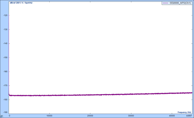
Figure 2. Spider-80Hi input noise floor
Just as a wide input dynamic range allows a DAQ to capture both small and large signals with accuracy, a wide output dynamic range ensures that the controller can reproduce those same signals with equal precision. In vibration control, this capability is essential since an output channel can be used to drive a shaker. It is necessary that this signal is clean and undistorted so that it can match the intended test profile. A controller with a high output dynamic range and linearity prevents distortion across the full range of operation, ensuring stable control, accurate test reproduction, and reliable system performance.

Figure 3. Spider-80X output dynamic range. The output channel is used to generate a ~500 nanovolt signal at 1 kHz.
Total Harmonic Distortion quantifies the harmonic content that is added to a signal by a system. Ideally, when a DAQ measures a pure sine tone, the output should be a pure sine tone, but in real hardware nonlinearities may cause distortion that generates harmonics at multiples of the fundamental frequency. A system with low THD ensures that measured harmonics are real and introduced by the input signal and not by the system.
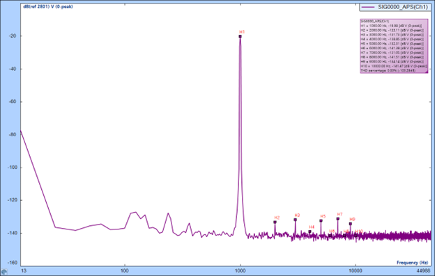
Figure 4. THD with the Spider-80X at 1 kHz.
Crosstalk refers to the unwanted coupling between channels, and it occurs when the signal from one channel unintentionally interferes with another channel. For multi-channel DAQs and vibration controllers, maintaining low cross talk is critical to ensure each channel can accurately measure sensors or actuators.
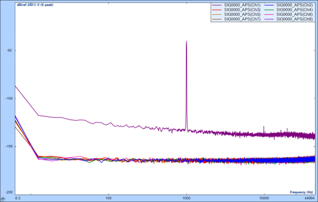
Figure 5. Crosstalk among 8 channels on the Spider-80X
Common Mode Rejection is the ability of a DAQ to reject noise or interference that is present on both the positive and negative inputs of a differential channel. It determines how well a DAQ can extract the true signal from a sensor even in the presence of strong electrical noise. In real-world environments, long cables, ground potential differences, and EMI can induce unwanted voltage on a pair of differential signal lines. A system with high CMMR is able to effectively cancel disturbances that appear on both lines of differential sensors.
With improvements in dynamic range, THD, crosstalk, CMMR, the latest generation of Spider hardware represents a significant leap forward in data acquisition and vibration control technology. These advancements ensure greater signal fidelity, lower noise, and more accurate measurements.