
Brake Rotor Modal Testing with Crystal Instruments "Spider" Data Acquisition System

Modal testing is a common method to determine the characteristics of an object through exciting the structure to a certain vibration level and obtaining its resonance frequencies.
At resonance frequency, the response is much greater than from other frequencies. It is important for a brake system to keep vibration under control during operation because excessive vibration while braking could cause driver discomfort, premature and irregular tire wear, and stress on steering and suspension components. Fundamentally, a brake system utilizes friction to slow down a vehicle. When using the brake caliper to press the brake pad against rotors to create high friction, unwanted vibration may occur.
One of the common ways to determine the resonance frequency of a system is to perform a Modal test. Modal testing can be done by using a forced impact hammer and an accelerometer. The hammer will measure the force being used to excite test object; while the accelerometer measures response. From this, we can get the Frequency Response Function and determine the resonance frequency.
As an example, we used a real Brake System for this Modal test. The setup is simple. Accelerometers are attached to test article and a Force Impact hammer is used to measure excitation.

Some people may want to excite the test subject with strong impact; however, this is a common mistake. It only takes a light tap to excite the structure to its resonance. A heavy impact may result in creating the impact more than once within an instant. Excessive force may overload sensors and saturate the response. Furthermore, it is important to separate the test article’s vibration from other objects such as the table it is being placed on. One safe way is to hang test article with a string, but for industrial environment, placing the object on a piece of soft foam is enough to separate this vibration from the table.
Using the Crystal Instruments Spider data acquisition system, we’re able to configure the trigger function to capture excitation and response for every impact made. Crystal Instruments’ EDM (Engineering Data Management) software can configure the system to capture the impact when the response reaches a defined level. When the impacts are made, EDM will save the signals and process the correlation between excitation and response signal to provide the Frequency Response Function (FRF). Of course, looking at the FRFs alone is not enough to justify whether the response actually correlates to the excitation. Hence, we have Coherence function to look at this relationship. If Coherence value is at 1, that means the correlation between excitation and response is 100% linear.
Front Rotors: (1 Excitation, 2 Responses)

From the result here, we can see 6 resonances of the Front Rotor. For example at 1943.75 Hz, the Coherence is 0.998, so we can safely assume that Excitation and Response correlation is linear and accurately presents resonance. Similarity, we performs the same method for Calipers and Brackets as well.
Results
- Front Rotor: Demonstrates 6 resonance modes with Coherence between 0.88 and 0.98
- Front Caliper: Coherence is less than 0.5 after 1st mode. No more resonance observed after.
- Rear Caliper: Coherence is less than 0.5 after 2nd mode. No more resonance observed after.
- Rear Rotor: Coherence is less than 0.5 after 5th mode. No more resonance observed after.
- Front Bracket: Coherence is less than 0.5 after 1st mode. No More resonance observed after.
| Mode 1 (Hz) | Mode 2 | Mode 3 | Mode 4 | Mode 5 | Mode 6 | |
|---|---|---|---|---|---|---|
| Caliper Front | 1719.73 | - | - | - | - | - |
| Caliper Rear | 2375.00 | 4570.31 | - | - | - | - |
| Rotor Front | 801.25 | 1943.75 | 3146.25 | 4413.75 | 5653.75 | 7042.50 |
| Rotor Rear | 737.50 | 1483.12 | 2507.50 | 3818.75 | 5030.00 | - |
| Bracket Front | 4984.76 | - | - | - | - | - |
The information is useful for multiple applications depending on design criteria and purpose. With the modal information, we can figure out the modal shape of the rotor. Theoretically, if we can measure acceleration and/or displacement over various locations of rotors, we will have various FRFs on the objects’ locations. Plotting FRFs’ magnitude and phase along the rotor model can show the modal shape. For example, if we use this information to figure out the flatness of rotor which would result this brake system to resonate, we can do simple calculations.

From FEA analysis, the expected modal shape for brake rotors are typically as figures shown above (as courtesy from Triches, Gerges &
Jordan, 2004 Federal University of Santa Catarina, Mechanical Engineering Department). Noise and vibration from a brake system can be
caused at resonance. If flatness Δ can be defined as distance between two uneven points on surface along rotor surface circumference,
we can determine this distance with simple specs from the vehicle.
Assumptions:
1. Uniform density
2. Balanced wheels and tires
3. Flatness Δ is uniform without other uneven defects on surface.
Given wheels, tires, and rotor dimensions, we can figure out RPM values at x speed, hence map these variables with the resonance
found from our modal test to find Flatness Δ at speed x.

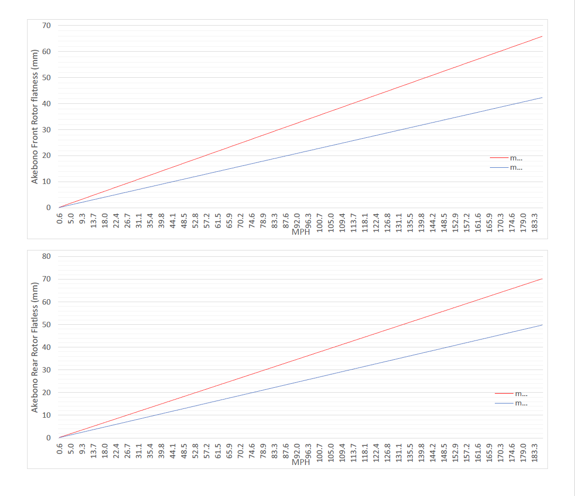
From our quick analysis of the example above, we found that, while traveling at 100 MPH (160.9 KPH) with the current wheel/tires
specs, the Rotors will go into First Mode of resonance if the Flatness Δ is 1.39-0.90 in and 1.49-1.05 in (Front and Rear respectively).
Other Resonance Modes may present if the Flatness Δ value is small enough to present Fcycle at certain speed. Simply reverse engineering the calculation above can figure this certain speed by certain Flatness Δ value.
From our calculation, we can theoretically determine Flatness Δ with respect to Velocity the vehicle will travel. Keep in mind that the
Flatness Δ here is relative; if Flatness Δ value is small enough to create multiple cycle within 1 rotation, we might have aliasing-like effects
in which higher resonance modes would occur.
For more information on Crystal Instruments' Dynamic Signal Analyzers, go here.
REFERENCES
Triches, M. J., Gerges, N., & Jordan, R. (2004). Reduction of Squeal Noise from Disc Brake Systems Using Constrained Layer Damping.
ABCM, 9.