
Understanding the Frequency Signature of a Head Expander
Head expanders are commonly used for vertical environmental testing. The purpose of the head expander is to extend the surface area of the shaker top to accommodate units under test (UUTs) with large dimensions for mounting and testing. One of the key parameters is the working frequency range associated with each head expander. The upper frequency is often used instead of the first resonance frequency of the head expander in vibration control tests.
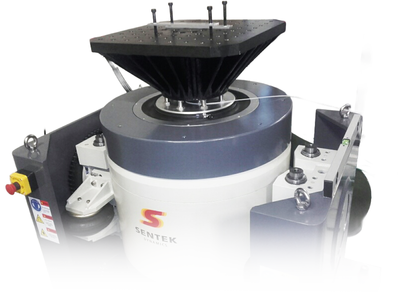
The following photo shows modal analysis carried out on a Sentek Dynamics HES1200M-1000/560 head expander. The head expander dimensions are 1200 x 1200 mm in a square format. The head expander was secured on top of a Sentek Dynamics model H10056A 100 kN shaker.

Figure 1. Sentek shaker assembly
To identify the frequency response characteristics of this head expander, the modal test is carried out with the head expander installed on the top of the shaker armature. The reference measurement point is chosen on the armature and is indicated with the placement of an accelerometer, as illustrated in the following photo.

Figure 2. Reference accelerometer mounted on the shaker armature
The boundary condition is the same as when the head expander was installed on top of the armature. The transmissibility of the top plate to the armature reference measurement point will show the amplification and attenuation of the head expander. The amplification (resonance points) and attenuation will illustrate the nature of the head expander and the maximum working frequency the user can assign for testing.
The top plate of the head expander is meshed into 7 by 7 points, with a total of 49 measurement points. The test is conducted through the Spider-80M system by roving sensors to cover 7 measurement points each time.

Figure 3. Measurement points on top of the head expander
Using the MIMO FRF test in the EDM Modal suite, a broadband random excitation is used to excite the head expander. Through various experimental runs, a burst random signal type is selected. The frequency range is 2.3 kHz, which covers the frequency components up to 2000 Hz.

Figure 4. EDM Modal MIMO FRF test measurement
The following are FRF signals from all 49 measurement points:

Figure 5. 49 Overlaid FRF signals from modal data selection
Using the EDM Modal curve fitting process, the following modes are identified.
Several major mode shapes are observed:

Figure 6. First mode

Figure 7. Third mode

Figure 8. Fourth mode

Figure 9. Sixth mode
This was the first round of modal testing carried out on the HES1200 head expander. The next step is to conduct the damping treatment of the head expander. Afterwards, the same modal test will be repeated to compare FRF signals and modes to observe any changes in mechanical characteristics.


VIB-102 Vibration Fixture Design Seminar
September 23-24, 2025 | Kannapolis, North Carolina
Overview: Introduction to the basics of vibration qualification testing. Review of MIL-Specs and requirements that define vibration tests. Review of vibration shakers, amplifiers, instrumentation and vibration controllers. Critical information on designing fixturing to interface the test article to the shaker. Tips and best practices including review of techniques for determining dynamic response using test (impact modal) and analysis (Finite Element). Demonstration of vibration qualification testing. Valuable to technicians, test engineers, test lab managers as well as design engineers and test conductors.
Overview of Vibration Qualification Testing
How structures vibrate - Forced vibration plate
Background on vibration testing
Vibration shakers - basic shaker sizing
Vibration signal processing terminology
Types of vibration test - vibration controller
Vibration fixture design considerations – FEMA, Impact Modal, Visualization
Shaker fixture dynamic interaction
Demonstration
$2400 registration fee, use promo code PETE2025 to save 15%