
Modal Analysis of Hood Fan Using EDM Modal
The experimental object in this modal test is a hood cross-flow fan with an overall structure that includes a roulette wheel, rotor frame and cross-flow blades that are composed of metal materials. The fan is hung using bungee cords to imitate free-free boundary conditions.
The experimental goal is to study the fan axial mode, natural frequency, mode shape, damping ratio and other mode parameters.
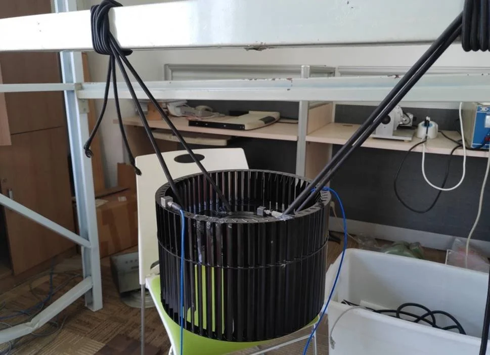
Figure 1. Square Hood Crossflow Fan
The hardware system used for this modal test is the Spider-80X vibration analyzer, a PCB lightweight single-axis accelerometer, and a PCB modal impact hammer. EDM Modal software was used for the modal testing and analysis workflow.
Table 1. Test systems and software
| System Component | Model | Specification | Comment |
|---|---|---|---|
| Data acquisition and analysis systems | Spider-80X | 8 channels | Crystal Instruments |
| Force hammer | 086C03 | 500 N | PCB |
| Acceleration sensor | Single-axis 333B30 | 2×100 mV/g | PCB |
| Software | EDM Modal | 9.0.1.11 | Crystal Instruments |
The geometric model of the structure is built using EDM Modal and a total of 52 measurement points were laid out to represent the measurement grid as shown below.
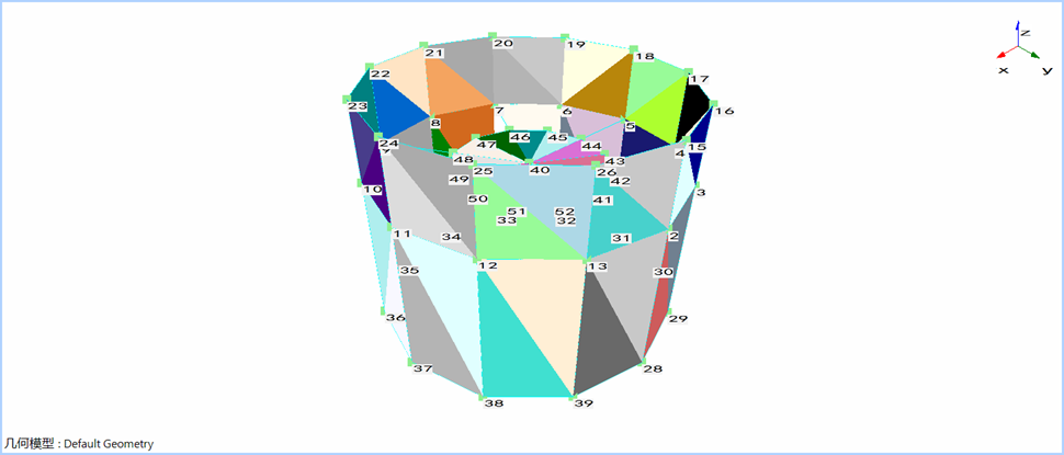
Figure 2. Geometric model of the structure
A roving excitation with one fixed accelerometer was used to execute this modal test without inducing any mass loading effect. One complete row of the FRF matrix as illustrated below with this approach.
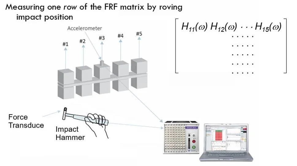
Figure 3. Schematic Diagram of the Roving Excitation Hammer Impact Test
The modal data selection tab overlaps the measured FRFs and assists in observing the resonances and anti-resonances within the desired frequency range as shown below.
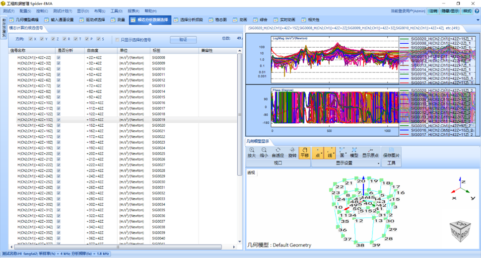
Figure 4. Test Data Preview
The latest Poly-X modal parameter recognition algorithm (p-LSCF) is used and the first six modal results (i.e., frequency, damping and mode shape information) are analyzed.
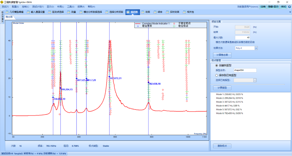
Figure 5. Stability Diagram
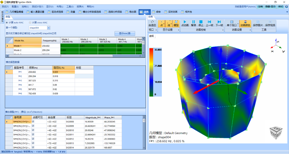
Figure 6. Modal Results of Hood Fan
The Modal Assurance Criterion (MAC) is used to check the consistency and correlation between the modes. The diagonal elements of the MAC matrix of this modal experiment are close to 1 and the values of non-diagonal elements are small. Users can conclude that the vectors of each order are better orthogonal and the decoupling between the modes is better.
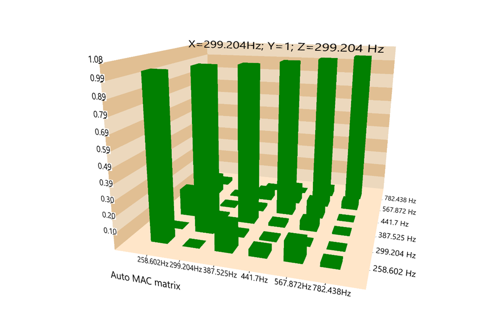
Figure 7. Modal Assurance Criterion (MAC) Chart
Information regarding the first 6 modes is provided in the following table:
| Modal order | Frequency (Hz) | Damping ratio (%) | Comment |
|---|---|---|---|
| #1 | 258.602 | 0.835 | Circumferential bending and twisting Composite vibration |
| #2 | 299.204 | 0.918 | Radial vibration |
| #3 | 387.525 | 0.315 | Circumferential bending vibration |
| #4 | 441.7 | 0.89 | Circumferential bending and torsion Composite vibration |
| #5 | 567.872 | 0.82 | Roulette wheel local vibration is dominant |
| #6 | 782.438 | 0.638 | Circumferential bending vibration |
The experimentally measured 6th-order mode has complex vibration characteristics. The #1 and #4 modes are represented by circumferential bending and torsional composite vibrations from the mode shape. The #2 mode is characterized by radial vibration, and there is a relative movement between the wheel and the impeller. The #3 and #6 modes are manifested as bending vibrations without torsional vibration. The #5 mode is expressed as the local vibration mode of the roulette wheel.
Through the modal analysis of the cross-flow fan, the structural design can be optimized. Since the fan is driven by an electric motor, it is easy to cause torsional resonance, so it is particularly necessary to pay attention to the composite modes with torsional vibration of #1 and #4 in order to avoid the resonance frequency; from #5 local mode, it can be seen from the mode shape that the relative deformation is larger, and the stress may be larger, and it is recommended to strengthen the stiffness of the roulette mechanism.
Each mode shape can be found in the following pictures:
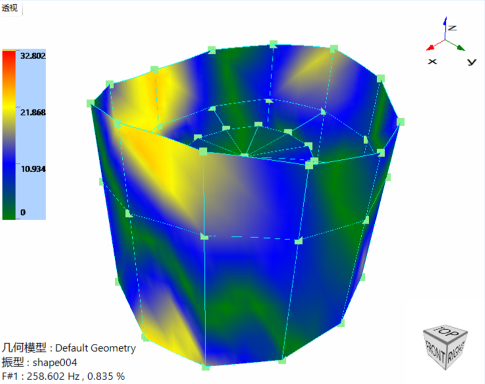
Figure 8. #1 Mode Shape
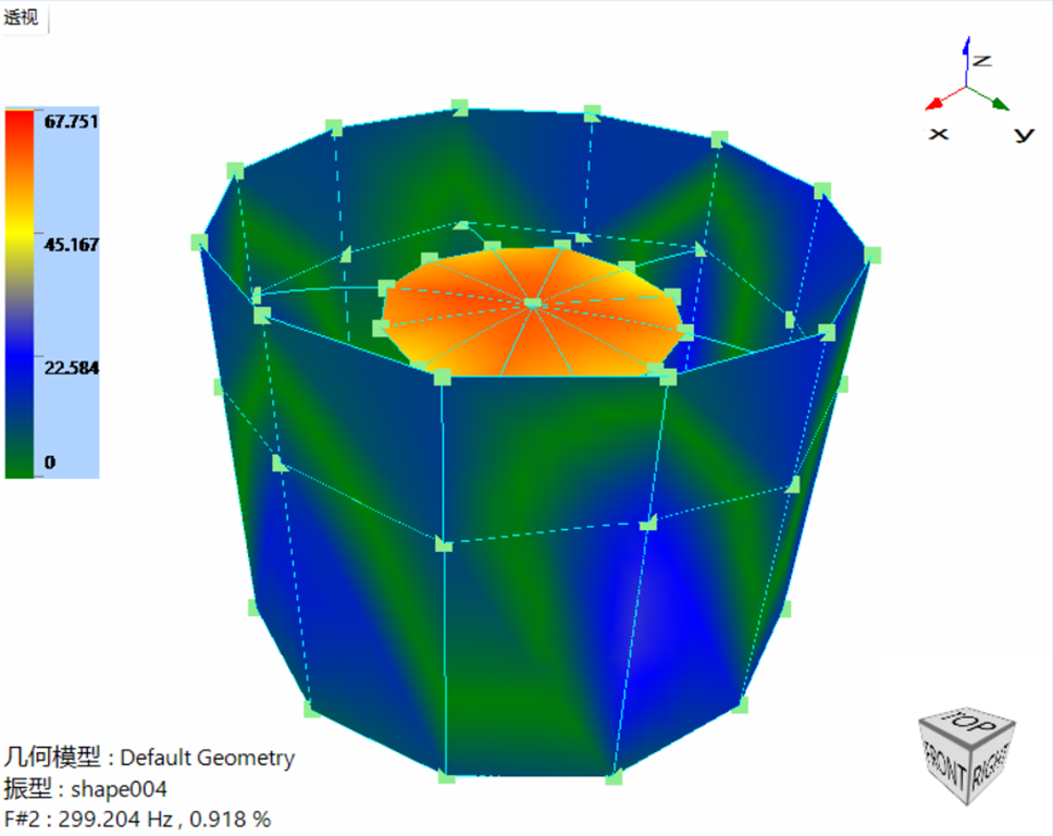
Figure 9. #2 Mode Shape
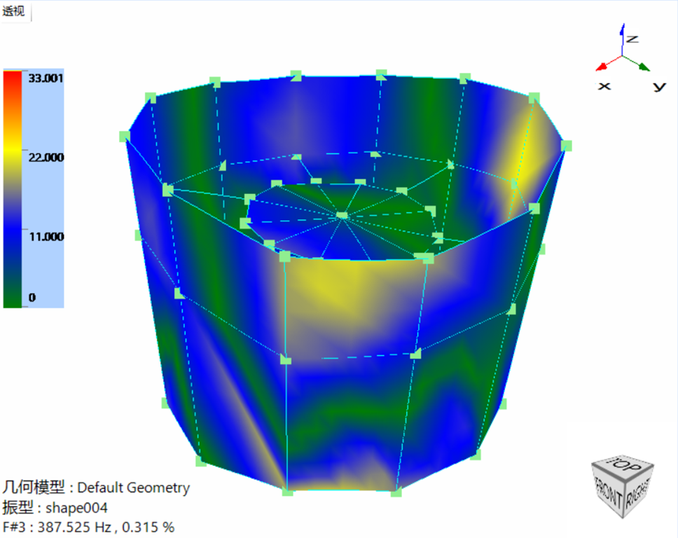
Figure 10. #3 Mode Shape
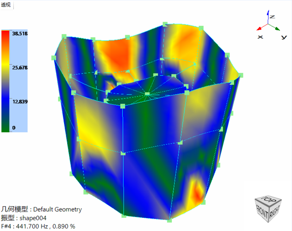
Figure 11. #4 Mode Shape
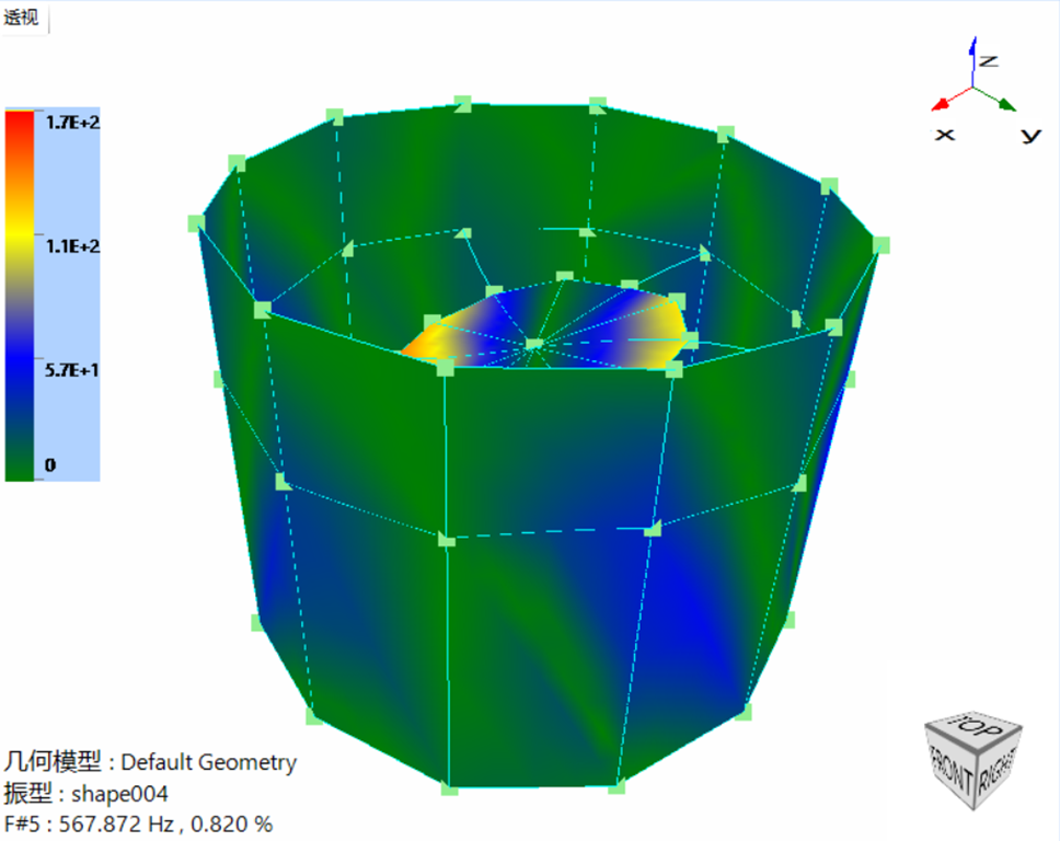
Figure 12. #5 Mode Shape
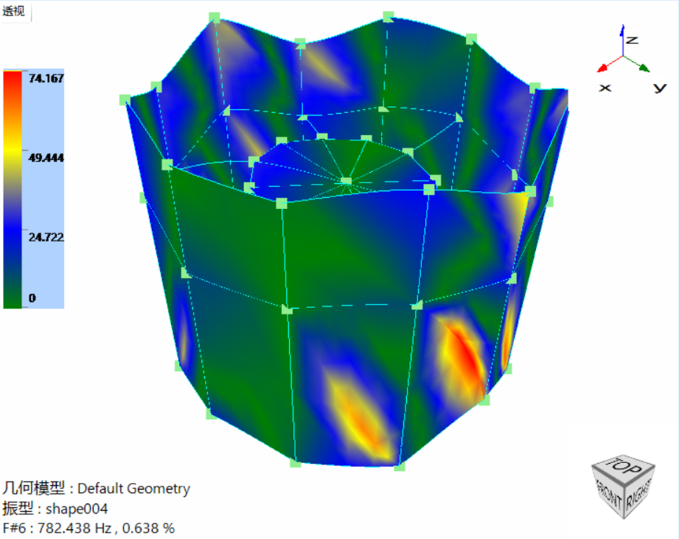
Figure 13. #6 Mode Shape