
Modal Testing to Improve Team Icewave’s Battle Performance

Written in collaboration between PCB Piezotronics, Inc., Crystal Instruments, and Team Icewave
Introduction
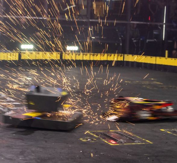
Icewave is a heavyweight robot designed by Marc DeVidts for robot combat competitions (Figure 1). Icewave’s claim to fame is its horizontal spinner powered by the competition’s only Internal Combustion Engine, which is where Icewave got its name. Icewave is also rumored to be the loudest robot due to its use of the internal combustion engine. Icewave is currently participating in BattleBots® Season 6, which airs on the Discovery Channel / discovery+ (Discovery Communications, LLC). BattleBots is recorded in Las Vegas, is viewed in over 150 countries, and has over 60 teams from across the globe who are competing for the title. The top combat robot takes home the Giant Nut, which is prominently shown at the beginning of each airing.
Each match is timed for three (3) minutes and takes place in the Battle Box, a 48’ x 48’ arena designed to protect the drivers, officials, referee, and audience. It also includes several added obstacles that drivers can use to damage the opposing robot. As long as the match doesn’t result in a Rules Violation Forfeit, the match will end in one of two ways. The first is a knockout, where one robot leaves another incapacitated due to the amount of damage it’s inflicted. The referee will count down from 10 once a robot is immobile, and if there is no movement, it is considered a knockout. The second way comes down to a judges’ decision and occurs when both robots are able to combat for the full three minutes. There are three judges who use a scoring system to determine the winner: five potential points for damage, three potential points for aggression, and three potential points for control of the match. Each judge adds up their scoring for each robot and awards the match to the robot that scores the highest. If all three judges score the same robot as the winner, it is a unanimous decision. If the count is 2:1, that is considered a split decision. How a robot wins a match can determine if it makes it to the final tournament, called the Top 32. This becomes a single elimination tournament and the winner of the Top 32 becomes the Tournament Champion, and they win the Giant Nut.
Icewave is powered by a 15 HP 2-stroke internal combustion engine from a Husqvarna concrete saw that drives a 54 lb. hardened S7 steel blade, rotating at 200 mph at the tips.

Figure 1: Icewave Bot Suspended in Modal Test Frame
Icewave has an overall record of seven wins and six losses. Marc DeVidts, Icewave creator and team lead, believes some of the losses may have been due to the blade not impacting opponents effectively. Because of the power behind Icewave, some of these losses can be attributed to self-inflicted damage from its own rotating horizontal blade. The modal testing will be used to help increase striking effectiveness.
Examination of the horizontal blade through vibration testing to identify the natural (modal) frequencies could provide useful clues as to how performance might be improved. Such vibration testing is typically performed using a shaker or impact hammer. In this instance, vibration testing was performed with an impact hammer.
Test Setup and Layout
An indoor laboratory was chosen to perform all testing. Temperature was maintained at approximately 70°F (21°C). Icewave was suspended via four bungee cord configurations inside an open frame. Connection to Icewave was achieved by attaching each bungee cord configuration to a cord looped through an eye bolt secured to its body. The opposite end of each bungee cord configuration was attached to a cord looped over the top rung of the open frame. 30 PCB Piezotronics ICP accelerometers (Model 333B30) were stud or epoxy-mounted to Icemaker with coaxial cables (PCB Model 002C10) running back to a Crystal Instruments Spider-80Xi 32-Channel Data Acquisition System (DAQ) with EDM Modal Software. Excitation of the structure was achieved using a PCB modal hammer (Model 086C03).
Equipment Selection
Sensors
In modal analysis applications, the general operating requirements are low acceleration signal levels, low frequencies, high channel counts and long cable runs. This requires sensors designed specifically for modal testing with good resolution, low frequency amplitude and phase, small size, flexible mounting and TEDS.
The above considerations led the researchers to select PCB’s Model 333B30 accelerometers for this test, as its specifications were a great match. Its low impedance and constant current operation ensures that signal levels are immune to factors that may introduce environmental noise.
Guidelines for selecting accelerometers for modal testing generally state to choose one with 100 mV/g sensitivity with approximately a milli-g resolution in a moderately small package (typically 5 grams or less). This minimizes the mass loading effect of the sensor. Model 333B30 also has a solid track history in modal testing, including similar structures as rudders, helicopter and turbine blades.
Hammer
PCB’s Model 086C03 Modally Tuned® ICP® instrumented impact hammer features a rugged force sensor that is integrated into the hammer’s striking surface. “Modal Tuning” is a feature that ensures the structural characteristics of the hammer do not affect measurement results. This is accomplished by preventing hammer resonances in the frequency range of interest from corrupting the test data, resulting in more accurate and consistent measurements.
The force sensor provides a measurement of the amplitude and frequency content of the energy stimulus that is imparted to a test object. Accelerometers are used in conjunction with the hammer to provide a measurement of the object’s structural response due to the hammer blow. A variety of tips supplied with each hammer permit the energy content of the force impulse to be tailored to suit the requirements of the item under test.
Using multi-channel data acquisition and analysis software, the test engineer is able to ascertain a variety of mechanical properties leading to an understanding of an object’s structural behavioral characteristics. Items analyzed can include resonance detection, mode shapes, transfer characteristics, and structural health via crack and fatigue detection.
Excitation Method
Of special note with modal accelerometers is the consideration of phase. Channel to channel phase matching throughout the measurement system is paramount for modal testing in the global parameter estimation generated from the measured frequency response data base. With global parameter estimation, the consistency of the frequency response function (FRF) database in terms of natural frequencies is also important. For this reason, it is also advised to instrument all desired measurement points simultaneously, thereby providing consistent mass distribution of the sensors on the test structure. Excitation is achieved by moving the impact hammer about the structure under test. This excitation strategy is known as the Roving Hammer Technique.
The older practice of roving a small set of accelerometers about a structure (Roving Accelerometer Technique) runs the risk of shifting certain component resonances as they are loaded and unloaded with the variable mass distribution of the “roved” set of accelerometers. This results in an inconsistent FRF database which challenges the parameter estimator, as it expects resonances to be consistent, global properties. An additional benefit of instrumenting all measurement points is the reduction of measurement set time. Essentially the measurement process takes a “snap shot” of data in time ensuring that other variances (ex. visco-elastic properties that can change with temperature, etc.) are consistent in the measurement database.

Figure 2: Placement of 333B30 Accelerometers
Bending Modes
Having measured both the excitation and the vibration of Icewave’s arm, the collected data forms a Frequency Response Function (FRF) data set. This data set gave researchers the capability to identify the modal parameters—natural frequencies, damping, and mode shapes. Examples of these mode shapes are presented in Figures 3 and 4.
The first mode is the lowest frequency at which deformation of the structure occurs. In this instance (Figure 3), the bending mode frequency is 40 Hz. and the first torsion mode frequency is 345 Hz.
Figure 3: Planned Measurement Grid of 333B30 Accelerometers
Figure 4: 1st Bending Mode 40 Hz
Figure 5: 1st Torsion Mode 345 Hz
Conclusion
The models suggest combined bending and torsion modes of the striking arm reduces the potential of the destructive force imparted on an opponent.
Moving forward, the Icewave team will have multiple options to potentially improve striking performance in combat. One general approach would be to look at ways to “stiffen” the striking arm. This could be achieved by increasing the thickness of the arm and accepting any weight penalties, or by evaluating new materials for the arm that are less susceptible to torsion and that will keep a better edge.
A third option would involve modifying the basic design of the arm on the bot. Torsion box physics might be turned to, as a lighter arm constructed with ribs will improve stiffness, yet it begs the question if it will deliver the force needed to incapacitate opponents.
Click to download “Modal Testing to Improve Team Icewave’s Battle Performance”